High-density fiber connectivity that stays understandable at the rack.

Plan data-center fiber connectivity with controlled polarity, fiber type, port maps, lengths, labels, insertion-loss evidence and rack-ready packing.

Send Your Requirements
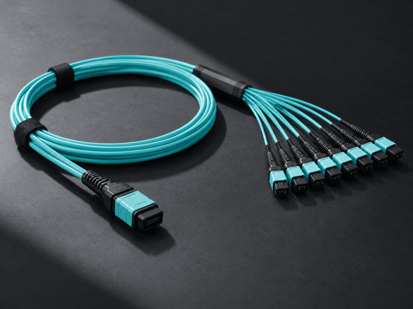
MPO trunk cable and high-density fiber connectivity prepared for a data-center rack

Start with equipment ports and the complete channel.

A data-center cable order should connect an equipment map to a physical assembly. Transceiver interfaces, breakout architecture, fiber category, lane assignment, polarity, cassette design and patch-panel orientation all affect whether the delivered components can form the intended channel.

FiberXi supports the passive connectivity supply scope. The customer remains responsible for active-equipment compatibility, channel design and commissioning, while the released order defines the assemblies, labels, optical evidence and packing needed at the rack.

MPO / LCHigh-density interfaces
A / B / CControlled polarity methods
OS2 / OM4Application-selected fiber

Control the lane map before comparing assembly prices.

A quotation becomes meaningful only after every supplier prices the same end-to-end interface and evidence boundary.

01

Equipment and topology

Identify switches, optics, patch fields, cassettes and cross-connects, then document every mating point in the planned channel.

  • Transceiver connector and lane count
  • Direct-connect, interconnect or cross-connect architecture
  • Panel, cassette and adapter orientation
02

Fiber category and reach

Select OS2 or an appropriate multimode category from the active-equipment requirement, wavelength, reach and installed channel rather than jacket color alone.

  • Equipment-supported fiber and wavelength
  • Permanent-link and patching distances
  • Channel loss allocation and future migration assumptions
03

Polarity and port identity

Release one end-to-end map showing fiber positions, key orientation, pinned or unpinned interfaces and duplex transmit/receive presentation.

  • Method A, B or C where applicable
  • MPO gender, keying and breakout sequence
  • Rack, panel, port and endpoint labels
04

Evidence and rack delivery

Define factory inspection at the assembly level and site acceptance at the installed-channel level, then group packages for the actual deployment sequence.

  • Endface and optical test record scope
  • Length, label and connector reconciliation
  • Rack, row, room or phase-based packing

Move from logical ports to controlled assemblies.

01

Map the channel

List active ports, passive transitions, lane assignments, fiber category and allowed loss.

02

Release the assembly schedule

Confirm part numbers, polarity, lengths, labels, quantities, test fields and packing groups.

03

Verify before installation

Reconcile received assemblies with the port map and preserve cleanliness before mating.

Questions to close before quotation.

Should a buyer choose MPO polarity from the cable alone?

No. Polarity is an end-to-end channel property involving trunks, cassettes, harnesses, adapters and patch cords. Release the complete map before ordering individual assemblies.

When is OS2 preferred over OM4?

The decision depends on active equipment, wavelength, reach, migration plan, installed infrastructure and economics. Follow equipment requirements and the engineered channel rather than a universal preference.

What factory evidence is useful for preterminated assemblies?

Buyers can define connector identity, length, endface inspection and insertion-loss records for an agreed population. Methods, reference conditions and report fields should be stated before quotation.

Can assemblies be packed by rack or row?

Yes, when the buyer provides a stable rack, row, panel and phase schedule before labels and packaging are released. The packing list should use the same identifiers.

Have a port map or data-center cabling schedule?

Send the topology, equipment interfaces, fiber type, lengths and labeling rules for a quote-ready assembly review.

Get a Quote